Ladder Logic Programming Tutorial STEP 5
![]()
![]()
Ladder Logic Programming Tutorial STEP 5
|
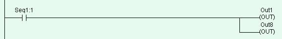
Circuits #3 to #6 are similar to one another. They make use of the Sequencer to turn on the Outputs 1 to 8 to create a pattern of "running lights" when executed. The label "Seq1:1" of the contact in Circuit #3 represents Step #1 of Sequencer 1. Remember that each sequencer can have up to 32 steps (Step #0 to 31), with each step individually accessible as a contact. A normally-open contact "Seq1:1" will be closed whenever the step counter of Sequencer 1 reaches number 1. Likewise a normally-closed contact "Seq5:20" will be opened when the step counter of Sequencer 5 reaches number 20.
To create the normally-open contact "Seq1:1",
left-click on the ![]() icon. When the I/O table pops up, scroll to the
"Special Bit" table and select the item #1 "SeqN:x". When prompted to
select a sequencer choose "Sequencer 1" and another dialog box will open up for
you to enter the specific step number for this sequencer. At this point, you should enter
the number "1" since we are using Step #1.
icon. When the I/O table pops up, scroll to the
"Special Bit" table and select the item #1 "SeqN:x". When prompted to
select a sequencer choose "Sequencer 1" and another dialog box will open up for
you to enter the specific step number for this sequencer. At this point, you should enter
the number "1" since we are using Step #1.
We have thus far been creating ladder circuits only by clicking on the ladder icons. A short-cut method of choosing elements to be created without using the mouse does exist. Observe the icon carefully and you will notice a small numeral at the lower right hand corner of each icon which correspond to the shortcut key. You may wish to try this short-cut for the remaining part of Circuit #3. Press the <7> key and the Output table will immediately pop up for selection of a coil. Pick "Out1" from the "Output" table and the "Out1" coil will be connected.
Circuits #4, 5 and 6 are very similar to Circuit #3 and you shouldn't have problem creating them. Complete these circuits and we are ready for some interesting simulation exercises. When you have created all the circuits, press <Enter> key or <ESC> key at the last blank circuit to end "Ladder Edit" mode.
Next, we want Seq1:4 contact to execute a "Custom Function"
(the abbreviation is CusF). A custom function is one that you can create to perform
very sophiscated control actions using the TBASIC language. The Custom function can
contains multiple TBASIC statements that gives the PLC extremely powerful capabilities
unmatched by many ladder-only type of PLCs. The Circuit we wish to create is as follow:
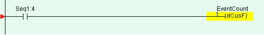
First, create the contact "Seq1:4" as per previous
circuits. Then left-click on the ![]() to connect to a Special Function coil. Select from the
popup menu the item "E: Diff. Up Custom Function" to create a
"Differentiated Up" version of Custom Function (For a full explanation of the
meaning of Differentiated Up", please refer to TBASIC Introduction The Custom function popup menu will appear for you
to select the Custom Function number you wish to insert. Up to 256 Custom functions can be
defined and you can click on the first custom function. as follow:
to connect to a Special Function coil. Select from the
popup menu the item "E: Diff. Up Custom Function" to create a
"Differentiated Up" version of Custom Function (For a full explanation of the
meaning of Differentiated Up", please refer to TBASIC Introduction The Custom function popup menu will appear for you
to select the Custom Function number you wish to insert. Up to 256 Custom functions can be
defined and you can click on the first custom function. as follow:
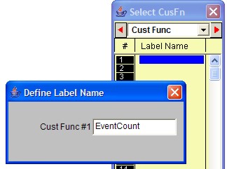 |
Since the custom function has not been defined with a label name, you will be prompted to give it a label name. The label name given to the CusF must be unique and are subject to the same limitations as that of the I/O label names. Lets enter the label name "EventCount" for function #1. Note: Label name for Custom function is optional and if you don't wish to use label name then the program will automatically assign it a name "Fn_#1" for function #1, "Fn_#2" for function #2, and so on. |
When the Custom Function editor has been opened, enter the following
text and then close the editor window by click on the ![]() or by pressing the <ESC> key. If you would like to
exit the editor window without saving the changes, click on the
or by pressing the <ESC> key. If you would like to
exit the editor window without saving the changes, click on the ![]() button.
button.
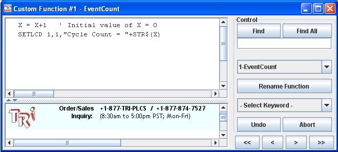
The purpose of this custom function is to keep a cycle count of the number of times the Sequencer has completed the complete sequencing and display the cycle count on the PLC's built-in LCD display (or on the Simulator's "View Variable" screen). This custom function should be run ONLY ONCE whenever the Seq1:4 contact closes, which is why the differentiated version of Custom function must be used in this case ( {dCusF}, not {CusFn})
We can make our program more comprehensive to other users by utilizing the "Comments" feature of i-TRiLOGI. Open the "Circuit" menu and select "Insert Comment". A comment editor window will be opened up to allow you to add your comments to any part of the circuit. When you are done with your comments, just press <ESC> key or close the comment editor window and the comments you just entered will be inserted between the circuits. Each comment occupies a circuit position and there is no limit to the number of lines a comment circuit may have. (However, if you wish to keep data file compatibility with the old DOS TRiLOGI Version 4.x you should limit the comment to no more than 4 lines per comment and each line should contain no more than 70 characters.)
A comment circuit may be moved around or deleted just like any other ladder circuits. If you wish to edit the comment, just double-click on it or press the <Spacebar> to open up the comment editor window. You can use the normal text editing keys such as left, right, up, down cursor keys, and <Ctrl-Left>, <Ctrl-Right>, <Del> and <Backspace> keys for editing the comment text.
Back to Step 4 ![]()
![]() Goto Step 6
Goto Step 6