Ladder Logic
Programming Tutorial STEP 6 ![]()
Ladder Logic
Programming Tutorial STEP 6 |
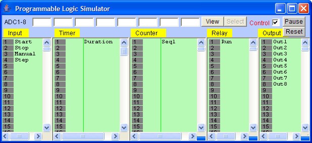
The stage has been set and the show is ready! Having completed the demo program, it is time to test if it works as intended using the built-in real-time programmable controller simulation engine. Open the "Simulate" pull-down menu and activate the command "Run (All I/O reset) - Ctrl+F9". i-TRiLOGI will immediately compile the ladder program and if no error is detected, it will instantly proceed to open up the "Programmable Logic Simulator" screen, as shown below:
If you have followed closely all the instructions during the creation of the demo program, you should not encounter any compilation error. However, if you do receive an error message, then please check your circuit against the picture shown in the assignment page, make all necessary corrections and then try again.
The simulator screen comprises 5 columns: Input, Timer, Counter/Sequencer, Relay, and Output. With the exception of the Relay table which contains up to 512 elements, and the Timer table which contains up to 128 timers, all other columns contain 256 elements each. Every column has its own vertical scroll bar. You can use the mouse to scroll each column independently to locate the desired I/O.
The label names for the inputs, outputs, relays, timers and counters defined earlier in the I/O tables automatically appear in their respective columns. To the left of each label name column is an "LED" lamp column which indicates the ON/OFF state of respective I/O. A red color lamp represents the ON state of an I/O, whereas a dark grey color lamp represents an OFF state. The I/O number is indicated in the middle of the lamp.
The simulator require the use of the mouse to work properly so it is important to remember the mouse button actions as follow:
Left Mouse Button Turn ON the I/O when pressed.
Turn OFF when button is released.Right Mouse Button Toggle the I/O when pressed once.
(i.e. OFF becomes ON and ON become OFF)
Our ladder program requires us to "push" the "Start" button momentarily. You can simulate this action by moving the mouse pointer to the "Start" label (or the LED lamp) and press the LEFT mouse button once and then release the button. The action starts!
At this time, notice that the relay "RUN" is latched ON and the timer "Duration" begins to count down from the value of 1000 every 0.1sec, and the Output #1-#8 are turning ON/OFF sequentially in a "running light" pattern. Sequencer "Seq1" in the "Ctr/Seq" column begins to count upward from 1 to 3 and then overflows to 0 and repeats continuously. For each step of the Sequencer, the corresponding Output will be turned ON. Our demo program will show a running light pattern starting from Outputs 1 & 8, then 2 & 7, 3 & 6 and 4 & 5 and then back to 1 & 8, 2 & 7.....
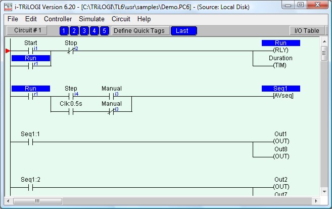
Now you should verify that the logic works as intended by observing the ladder diagram. You should notice that the "Run" labels in all circuits are highlighted as shown below:
The logic states of any I/O can be displayed on the ladder diagram directly. An Input, Output, Relay, Timer or Counter contact that is turned ON will have its label name highlighted in the ladder diagram. This feature helps greatly in debugging and understanding the logical relationship between each I/O. For example, from the above figure, we can see clearly that the "Self-latching" circuit for relay "Run" works as intended: when we first turn ON the "Start" input, "Run" will be energized and its contact which is parallel to "Start" will hold itself in the ON state, even if we subsequently turn OFF the "Start" input by releasing the button.
The timer coil "Duration", being connected in parallel to "Run" relay, will also be energized. However, its contact will only be closed after 100 seconds (when its present value counted to 0). To break the latched On "Run" relay, we must energize the "Stop" input momentarily to break the "power" flow. Try it now.
Let's restart the system by turning ON the "Start" input momentarily again. Next, we want to turn ON the "Manual" input. Move the mouse pointer to the "Manual" input and then press the right mouse button. "Manual" input will be "stuck at "ON" state even after you have released the right mouse button. Click on "Manual" button using the right mouse button again and it will be turned to OFF.
When "Manual" input has been turned ON, the running lights should stop. This is because the normally-closed contact of the "Manual" input in Circuit #2 is now turned OFF and the 0.5s clock pulse could not trigger the [AVseq] function anymore.
If you now left-click on the "Step" input, the running lights will move one step at a time in response to your mouse click. Observe the Seq1:x contact with respect to the counter value of Seq1 and the logic of this circuit become very clear instantly.
Observe that the timer "Duration" continues to count down every 0.1 second, and when it reaches 0, the "Duration" output coil label will be highlighted. You can use this timer to stop the program by connecting a N.C. "Duration" contact to Circuit #1. This is left as an exercise for you!
You can also observe the execution of the Custom Function #1 by clicking on the "View" button on the "Programmable Logic Simulator" screen and the following window will appear:
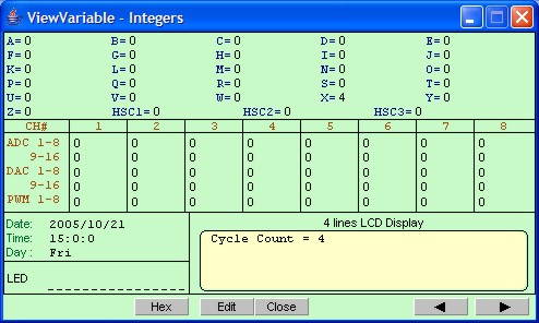
This screen shows the values of TBASIC variables A to Z and many other data. It also provides a simulated 4 lines LCD display that show case the action of the SETLCD statement contained in Custom Function #1. As you can see, the value of variable X used in the Custom function is also shown in the variable section. The value of X is converted by the STR$(X) statement into a string and displayed after the text string "Cycle Count = " at line #1, column #1 of the LCD area.
Summary
We have completed this hands-on session and have successfully created a simple ladder +BASIC program. We have also performed real time simulation to test the program's functionality. By now you would probably have a good appreciation of i-TRiLOGI's superb capability and ease of use and are ready to include i-TRiLOGI as an integral part of your programming needs.
![]() Go Back to Step 5
Go Back to Step 5