Using i-TRiLOGI Sequencers
A sequencer is a highly convenient feature for
programming machines or processes which operate in fixed sequences. These machines operate
in fixed, clearly distinguishable step-by-step order, starting from an initial step and
progressing to the final step and then restart from the initial step again. At any moment,
there must be a "step counter" to keep track of the current step number. Every
step of the sequence must be accessible and can be used to trigger some action, such as
turning on a motor or solenoid valve, etc.
As an example, a simple Pick-and-Place machine that can pick up a
component from point 'A' to point 'B' may operate as follow:
| Step # |
Action |
| 0 |
Wait for "Start" signal |
| 1 |
Forward arm at point A |
| 2 |
Close gripper |
| 3 |
Retract arm at point A |
| 4 |
Move arm to point B |
| 5 |
Forward arm at point B |
| 6 |
Open gripper |
| 7 |
Retract arm at point B |
| 8 |
Move arm to point A |
i-TRiLOGI Version 5 supports eight sequencers of 32 steps each. Each
sequencer uses one of the first eight counters (Counter #1 to Counter #8) as its step
counter. Any one or all of the first eight counters can be used as sequencers
"Seq1" to "Seq8".
To use a sequencer, first define the sequencer name in the Counter
table by pressing the <F2> key and scroll to the Counter Table. Any counter to be
used as sequencer can only assume label names "Seq1" to "Seq8"
corresponding to the counter numbers. For e.g. if Sequencer #5 is to be used, Counter #5
must be defined as "Seq5". Next, enter the last step number for the program
sequence in the "Value" column of the table.
Construct a circuit that uses the special function "Advance
Sequencer" [AVSeq]. The first time the execution condition for the [AVseq] function
goes from OFF to ON, the designated sequencer will go from inactive to step 1. Subsequent
change of the sequencer's execution condition from OFF to ON will advance (increment) the
sequencer by one step. This operation is actually identical to the [UPctr] instruction.
The upper limit of the step counter is determined by the "Set
Value" (SV) defined in the Counter table. When the SV is reached, the next
advancement of sequencer will cause it to overflow to step 0. At this time, the
sequencer's contact will turn ON until the next increment of the sequencer. This contact
can be used to indicate that a program has completed one cycle and is ready for a new
cycle.
Accessing individual steps of the sequencer is extremely simple when
programming with i-TRiLOGI. Simply create a "contact" (NC or NO) in ladder edit mode. When the I/O window pops up for you to pick a
label, scroll to the "Special Bits" table as follow:
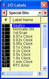
The "Special Bits" table is located after the
"Counters" table and before the "Inputs" table. Then click on the
"SeqN:x" item to insert a sequencer bit. You will be prompted to select a
sequencer from a pop-up menu. Choose the desired sequencer (1 to 8) and another dialog box
will open up for you to enter the specific step number for this sequencer.
Each step of the sequencer can be programmed as a contact on the ladder
diagram as "SeqN:X" where N = Sequencers # 1 to 8. X = Steps # 0 - 31.
e.g. Seq2:4 = Step #4 of Sequencer 2.
Seq5:25 = Step #25 of Sequencer 5.
Although a sequencer may go beyond Step 31 if you define a larger SV
for it, only the first 32 steps can be used as contacts to the ladder logic. Hence it is
necessary to limit the maximum step number to not more than 31.
Special Sequencer
Functions
Quite a few of the ladder logic special functions are related to the use
of the sequencer. These are described below:
Increment the sequencer's step counter by one until it overflows. This
function is the identical to (and hence interchangeable with) the [UpCtr] function.
The sequencer can also be reset to become inactive by the [RSseq]
function at any time. Note that a sequencer that is inactive is not the same as sequencer
at Step 0, as the former does not activate the SeqN:0 contact. To set the sequencer to
step 0, use the [StepN] function described next.
In certain applications it may be more convenient to be able to set the
sequencer to a known step asynchronously. This function will set the selected sequencer to
step #N, regardless of its current step number or logic state. The ability to jump steps
is a very powerful feature of the sequencers.
Although not available as a unique special function, a Sequencer may be
stepped backward (by decrementing its step-counter) using the [DNctr] command on the
counter that has been defined as a sequencer. This is useful for creating a reversible
sequencer or for replacing a reversible "drum" controller.
a. Driving Stepper Motor
A sequencer may be used to drive a
stepper motor directly. A two-phase stepper motor can be driven by four transistor outputs
of the controller directly (for small motors with phase current < 0.5A) or via
solid-state relays. The stepper motor can be driven using a sequencer that cycles through
Step#0 to Step#3 (full-step mode) or Step#0 through Step#7 (half-step mode). Each step of
the sequencer is used to energize different phases of the stepper motor. A clock source is
needed to drive the stepper motor through its stepping sequence. The stepping rate is
determined by the frequency (which is equal to 1/period) of the clock source.
Clock pulses with periods in multiples of 0.01 second can be generated
easily using the "Clk:.01s" bit and an [Upctr] function. For e.g., to generate a
clock source of period = 0.05s, use "Clk.01s" to feed to an [Upctr] counter with
Set Value = 4. The counter's contact (completion flag) will be turned ON once every 5
counts (0,1,2,3,4), which is equivalent to a 0.05 sec. clock source.
b. Replacing a Drum Controller
A
drum controller can be replaced easily by a sequencer if the timing of the drum's outputs
can be divided into discrete steps. Assuming a drum controls two outputs with the timing
diagram shown in the following figure:
This can be replaced by an 8-step sequencer. Step 1 (e.g
"Seq1:1") turns ON and latch Output A using [Latch] function, Step 2 turns ON
and latch Output B, Step 4 turns OFF Output A using the [Clear] function, and Step 6 turns
OFF Output B. All other steps (3,5,7,0) have no connection.
Assume that we wish to create a running light pattern which turns on
the LED of Outputs 1 to 4 one at a time every second in the following order: LED1, LED2,
LED3, LED4, LED4, LED3, LED2, LED1, all LED OFF and then restart the cycle again. This can
be easily accomplished with the program shown in Figure 6.9.
The 1.0s clock pulse bit will advance (increment) Sequencer #2 by one
step every second. Sequencer 2 should be defined with Set Value = 8. Each step of the
sequencer is used as a normally open contact to turn on the desired LED for the step. A
"Stop" input resets the sequencer asynchronously. When the sequencer counts to
eight, it will become Step 0. Since none of the LED is turned ON by Step 0, all LEDs will
be OFF.