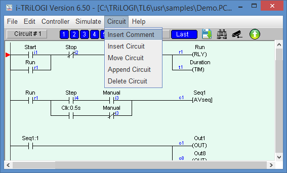
You are normally in the browser mode when you start up the program. The browse mode allows you to manipulate the whole ladder logic circuit as a single entity: you can view any circuit, make copies of it, move it to another location or delete it entirely. Each complete ladder logic "circuit" is given a circuit number. You should see a small red color marker showing you the currently selected circuit. The circuit number of the selected circuit is shown on the upper status line as "Circuit # xxx ".
Mouse Actions
Since i-TRiLOGI Version 6 and up runs under windowing environment, all usual mouse action applies. You can grab the vertical scroll bar to scroll to your desired circuit and click on it to select it. Double click on a circuit enters the Circuit Editing Mode which will be described later.
The functions of various keys in the browse mode are explained below:
<Spacebar> - Allows you to enter circuit editing mode for the currently selected circuit. If the selected circuit is a comment circuit, the comment editor will be opened automatically.
<F1> - Activates the context-sensitive help function to display on-line help.
<F2> - Opens the I/O Table to create the I/O Label Names
<F3> - Turns ON/OFF display of the I/O type and the physical I/O number for ladder logic contacts on the screen (The physical I/O number is now linked to the labelname). All ladder logic contact symbols are normally identified by their label names. However, you can also display an optional small literal to indicate the I/O types and number. e.g. i1=input 1, o12=output 12, r25= relay 25, t1= timer 1 and c5=counter 5.
<F5> - Refreshes the display. If for some reason the screen is garbled by incomplete circuit display, you can just press the <F5> key to redraw the screen.
<F7> - Opens any custom function. If the currently selected circuit contains a custom function, then it will be opened for editing. Otherwise i-TRiLOGI will ask you to select a custom function # from a menu.
<F8> - Compiles the i-TRiLOGI program to show the compilation statistics.
<F9> - Runs the simulator without resetting any I/O.
<Ctrl-F9> - Resets all I/Os and then runs the simulator.
<Ctrl-F8> - Resets all I/Os except inputs and then runs the simulator.
-
<F11> - Zoom Out (applies to ladder logic and custom function editors, monitoring and view variables screens)
-
<F12> - Zoom In (applies to ladder logic and custom function editors, monitoring and view variables screens)
-
<Up>/<Dn><PgUp> and <PgDn> keys - Use the up/down cursor keys to move the marker to other circuits and the "Circuit #" display at the upper status line will simultaneously reflect the change. If you attempt to venture beyond the screen, the logic editor screen will scroll. The <PgUp> and <PgDn> keys can be used to scroll one page at a time.
Navigating Circuits in Browse Mode
Although most of the time you will probably be navigating the ladder circuit diagram using the scroll bar or cursor keys to find the circuit that you are looking for, there exist several short cuts to enable you to quickly jump to specific circuits in the program. E.g. If you select "Goto" from the "Edit" menu, you will be prompted by a “Goto Circuit” window to enter the circuit number to jump to immediately. You can also call up the “Goto Circuit” window by pressing <Ctrl-G> key anytime.
If you have a large ladder program with multiple
rungs of circuits, then you will find the “Bookmark” feature very useful for
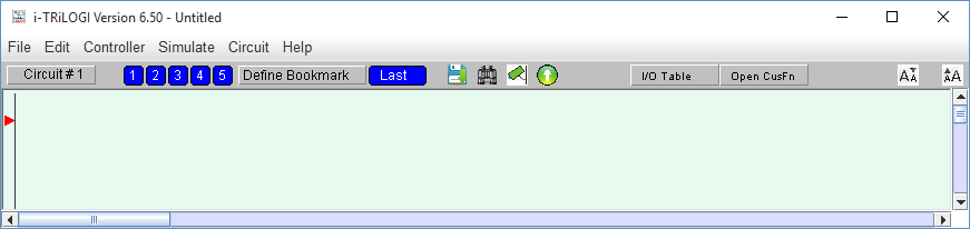
quickly jumping from one circuit to another. The bookmarks appear as blue button along the
top of the i-TRiLOGI editor windows: ![]() You can define up to five bookmarks by clicking on
You can define up to five bookmarks by clicking on ![]() ,
each bookmark corresponds to a specific circuit #. By default all 5 bookmark points to
circuit #1. Once you have defined the circuit # for a bookmark, then when you click on the
bookmark button the editor instantly jumps to the pre-defined circuit number.
,
each bookmark corresponds to a specific circuit #. By default all 5 bookmark points to
circuit #1. Once you have defined the circuit # for a bookmark, then when you click on the
bookmark button the editor instantly jumps to the pre-defined circuit number.
When you click on ![]() , the following window will appear
, the following window will appear
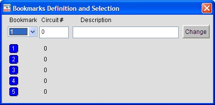
You can select the bookmark No. either from the choice box or by
clicking on the blue bookmarks ![]() ,
, ![]() Then enter or edit the circuit # to associate with
the selected bookmark. You can optionally enter/edit a description for the bookmark to
help you recall the purpose of that section of ladder circuit which the bookmark is
associated with. Then click the
Then enter or edit the circuit # to associate with
the selected bookmark. You can optionally enter/edit a description for the bookmark to
help you recall the purpose of that section of ladder circuit which the bookmark is
associated with. Then click the ![]() button to update the circuit # and description at
the corresponding bookmark location.
button to update the circuit # and description at
the corresponding bookmark location.
In i-Trilogi version 6.2 and later the bookmark you have created will be displayed in the corresponding ladder circuits. New programs created will set all the bookmarks to a default value of 0 so that no bookmarks are displayed until they have been manually created.
In i-Trilogi version 6.2 and later there is a feature that allows
you to immediately go the last circuit that was selected. This is implemented by clicking
on the ![]() button that is located beside the bookmark buttons,
which are described above. Whether you move to a new circuit by using the "Goto
Circuit" command or a bookmark or just by clicking on a circuit with the mouse, the
"Last" button will remember your last circuit position. This also allows you to
easily switch back and forth between two circuits an unlimited number of times because if
you don't select a new circuit after pressing the "Last" key, you will go back
to the circuit you came from.
button that is located beside the bookmark buttons,
which are described above. Whether you move to a new circuit by using the "Goto
Circuit" command or a bookmark or just by clicking on a circuit with the mouse, the
"Last" button will remember your last circuit position. This also allows you to
easily switch back and forth between two circuits an unlimited number of times because if
you don't select a new circuit after pressing the "Last" key, you will go back
to the circuit you came from.
Note: The bookmark definitions are saved along with the program body into the
“.PC6” file, which means that the bookmark that you defined for a particular
program can be recalled later when you open its “.PC6” file.
![]()
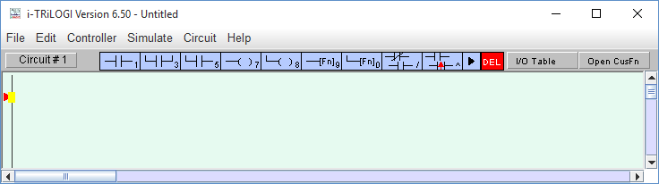
Trilogi 6.5/7.1 and up now includes a quick access toolbar that allows for the following single click operations:
1) File Save ![]()
2) Find Ladder Element/TBASIC
text ![]()
3) Online monitoring ![]()
4) Program Transfer ![]()
5) I/O Table Access ![]()
6) Custom Function access options ![]()
7) Zoom Out ![]()
8) Zoom In ![]()